MRO Interferometer (MROI)
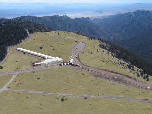 The Magdalena Ridge Observatory Interferometer (MROI) project’s mission is to develop a ten-element imaging interferometer to operate at wavelengths between 0.6 and 2.4 microns with baselines from 7.8 to 340 meters. The technical and scientific goals are to produce model-independent images of faint and complex astronomical targets at resolutions over 100 times that of the Hubble Space Telescope. The goal of the MROI is threefold, to support programs in:
- Astronomy
- Space situational awareness
- Education & outreach
The astronomical science program includes the following three areas:
- Star and planet formation
- Stellar accretion and mass loss
- Active galactic nuclei
The space situational awareness program includes imaging of Geosynchronous Satellites (GEOS), both commercial and military. More details on the key science mission for MROI can be found on our MROI science mission page. For basics of interferometry also check out our What is Interferometry page and the Glossary.
The design of the MROI project can be broken down into the following categories (click on each for more information):
MROI System ArchitectureThe MROI has been optimized to maximize the throughput and quality of light received within the beam combining laboratory. This will allow the MROI to observe targets more than 40 times fainter than has been possible with similar facilities.
Additionally, the array is reconfigurable to provide the ideal field of view and resolution for a given target. For example, if observing a fairly large object in the sky sampling of the object over a wider field of view may be required, while observing a very small and complex object a smaller field of view (think more ‘zoom factor’) and greater detail or resolution may be required. The use of multiple array configurations with the telescopes packed tightly together or farther apart allows for this trade off. Telescopes can be packed as tightly as 7.8 meters apart or as widely as 340 meters apart. The need for relocatable telescopes, a very tightly packed array configuration, and high throughput has resulted in unique designs for a number of subcomponents.
The Unit Telescope (UT)
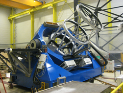
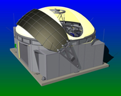
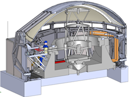
The MROI Unit Telescope (UT) is a movable unit made up of the telescope mount, 1.4-meter telescope, enclosure and ancillary systems required for routine operation. The telescope mount, designed by AMOS, is an elevation over elevation design with a fixed output beam implemented using only three mirrors. The enclosure, designed by EIE, features a rigid frame to support the telescope mount during relocation and a unique low profile dome and shutter to allow the telescopes to be placed in very close proximity without obscuring the field of view of an adjacent telescope.Ancillary systems included within the UT structure are a “fast tip-tilt” system, designed by the University of Cambridge, which corrects for first-order atmospheric distortions, an automated alignment system that aligns the telescope with the delay lines in the beam combining facility, a wide-field finder telescope, and controls and network infrastructure.
The Array Infrastructure & Beam Combining Facility (BCF)
The array infrastructure is a collection of subsystems necessary to allow the unit telescope (UT) to function at the site. These include the foundations, electrical, mechanical, and data communications systems. There are a total of 28 stations in the interferometer array on which telescopes can be placed, accommodating four standard array configurations. Each station has two foundations – one for the telescope mount and one for the enclosure. This is done to reduce vibrations transmitted from the enclosure to the light collected by the telescope. The foundations of the beam relay system that relay the signal to the BCF have similar isolation.The utility connections at each station include electrical power from an uninterruptible power supply (UPS), 1Gbps fiber optic connections for data communications, and chilled glycol (anti-freeze) loops for equipment and enclosure cooling. The array site also includes environmental monitoring equipment such as the central weather station.
The BCF has three distinct areas:
- Interferometer Control Area (ICA)
- Delay Line Area (DLA)
- Beam Combining Area (BCA)
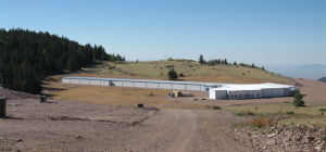
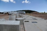
The ICA has the amenities that are required for staff operation at the site, such as a shipping & receiving space, electro-mechanical laboratory, optical laboratory, control room, kitchen, and office space. The DLA is a vibration-isolated, acclimatized space that houses the long-delay lines which are used to compensate for timing or path-length differences between the different telescopes and beam-trains in the array. The BCA is a vibration-isolated and thermally regulated space that houses the sensitive instruments which combine the light from the individual telescopes to resolve an image of an astronomical target.
The Beam-Train Subsystems
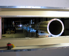
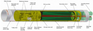
The beam-train subsystems are the mechanical systems that transport the light collected by each telescope to the measuring instruments located in the centralized Beam Combing Area (BCA). These systems include the Beam Relay System, Delay Line System, Beam Compressors, Alignment System and turning mirrors. From the star to the instrument table, only 12 mirrors are required so the light is reflected a mere twelve times. This is substantially fewer reflections than most other long-baseline interferometric facilities and is critical for system throughput since each reflection can result in 2% to 10% signal loss/degradation depending on the quality and condition of the mirror used. Each mirror and the total distance traveled by the light is precisely calibrated and aligned so that starlight from all the telescopes reaches the instrument at the same time and with the desired position and orientation to within less than one wavelength of the light. This also increases system sensitivity so as to enable the MROI to look at fainter objects than other interferometers to date.
The Instruments
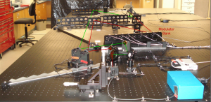
The core instrument that combines light from multiple telescopes is the fringe tracker, Infrared Coherencing Nearest Neighbor tracker (ICoNN). ICoNN combines light from adjacent telescope pairs and uses the collected information to synchronize the delay lines such that the light continuously arrives ‘in-sync’ from each telescope. This allows scientific measurements of the target star with a resolution comparable to that of a very large telescope (up to 340 meter in diameter in the largest array configurations).In addition to ICoNN, different wavelengths of light can be redirected to a second instrument. Both an infrared and visible combiner are currently in the design phase and will allow the MROI to rapidly and repeatedly collect information to generate images of astronomical targets in the respective wavelength bands. Finally, a fourth beam combining table will be provided to allow visitors to deploy their own instruments in the BCA.
The Control System
A goal of the MROI is to move interferometry from a “niche” or “fringe” science to a more mainstream method of performing astronomical research, similar to what has already happened in the radio community. The aim is to make rapid measurements on multiple targets over a night. This will build-up more observational points on each target, producing a higher quality image than has been possible with previous facilities. Performing rapid calibrations and observations requires a robust and intelligent controls infrastructure free of frequent human intervention.The Interferometer Control System consists of an intelligent Supervisory System and managed sub-systems. The Supervisory System will assist the Array Operator in running the MROI for the night’s observations.
The MROI team has finished most of the design work and is currently building all the major subsystems. The BCF was completed in early 2008. The first telescope and enclosure foundations were installed in 2011. The first telescope was installed on the array in 2018, and the second telescope is expected to be installed by June 2023. The fringe tracker beam combiner and cryogenic dewar (ICoNN) have been fabricated and the team has achieved stable laboratory fringes. Many other subsystems are at similar levels of development. Please look at our multimedia, our publications, and LIVE webcams pages for more up to date content.
For more information, please contact:
Michelle Creech-Eakman, Ph.D.
Project Scientist Interferometer/Physics Dept.
New Mexico Tech
801 Leroy Place, Socorro, NM 87801
MRO 575 835-6756, Physics 575 835-5809

